Class A vs Class B Amplifier: Understanding the Key Differences
Advertisement
This page compares Class A Amplifier Vs Class B Amplifier and mentions the difference between Class A Amplifier and Class B Amplifier.
Class A Amplifier

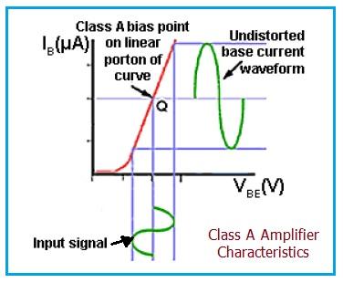
Class A Amplifier Characteristic
The main role of class-A bias is to keep the amplifier free from distortion by keeping the signal waveform out of the non-linear region which exists between 0V and 0.6V.
The figure-1 (above) depicts class A amplifier bias characteristics.
- Class A is used for low to medium power output stages.
- It is less used for high power output stages.
- It has poor efficiency compared to class B.
- They produce an output power of 50% (theoretical) and about 25 to 30% (practical).

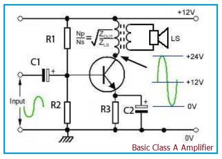
Basic Class A Amplifier
The figure-2 (above) depicts a basic class A Power amplifier. The efficiency of class-A PA is improved by placing an output transformer instead of a resistor as its load. With no signal, the quiescent collector current of the output transistor is about 50mA. When a signal is applied, the collector current will vary significantly above and below this specified level.
Class B Amplifier

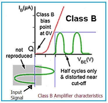
Class B Amplifier Characteristic
The figure-3 (above) depicts class B amplifier bias characteristics.
- The transistor in the circuit conducts for only half of each cycle of the signal waveform as there is no standing bias current (i.e., Iq is zero). Hence, efficiency is increased significantly compared to class A PA.
- Efficiency of 80% is possible theoretically with this bias, and about 50% to 60% is possible practically.
- It has better efficiency compared to class A.
Though the efficiency is higher, the downside is the transistor amplifies only half of the waveform, which produces severe distortion. To overcome this distortion, audio amplifiers use a push-pull circuit.

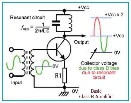
Basic Class B Amplifier
The figure-4 (above) depicts a basic class B power amplifier. In a push-pull output configuration, two identical but anti-phase signals from a phase splitter are provided to the bases of a pair of transistors. Here, each transistor feeds current to the load for half a cycle only. Later, the two half cycles are re-combined via a center-tapped transformer. This will produce a complete sine wave in the secondary coil.
Advertisement
 RF
RF


