 RF
RFBranch vs. Balanced vs. Circulator Duplexers: A Comparison
Advertisement
This article compares three common types of duplexers: the Branch duplexer, the Balanced duplexer, and the Circulator duplexer. We’ll explore their differences, advantages, and disadvantages.
What is a Duplexer?
Introduction:
A duplexer is a device that isolates the transmitter from the receiver during transmission and isolates the receiver from the transmitter during reception. Think of it as a microwave switch that directs signals between the antenna and the transmitter/receiver.
Functions of a Duplexer:
- Shared Antenna: Allows a single antenna to be used for both transmission and reception.
- Receiver Protection: Shields the receiver from the high power of the transmitter, preventing damage.
- External Interference Protection: Protects the receiver from strong transmissions from nearby radars or other wireless transmitters.
Types of Duplexers
The common types of duplexers are:
- Branch duplexer
- Balanced duplexer
- Circulator duplexer
Branch Duplexer
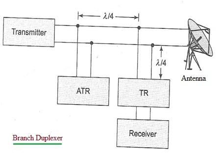
Figure 1: Block diagram of a Branch duplexer
-
Description: The Branch duplexer utilizes TR (Transmit-Receive) and ATR (Anti-transmit-receive) switches, typically implemented with gas discharge tubes.
-
Operation:
- Transmitting: When the transmitter is on, the TR and ATR tubes ionize (fire). The TR switch becomes a short circuit at the receiver end, preventing transmitter power from reaching it. At the transmission line, it acts as an open circuit, avoiding any attenuation of the transmit power. The ATR, placed λ/4 (quarter wavelength) away from the transmission line, also functions as a short circuit during firing but appears as an open circuit on the transmission line.
- Receiving: When the transmitter is off, the TR and ATR tubes don’t fire. The ATR acts as a short circuit across the transmission line, effectively disconnecting the transmitter. This allows received echo signals to reach the receiver.
-
Advantages:
- Lower cost
-
Disadvantages:
- Limited bandwidth
- Limited power handling capability
Balanced Duplexer
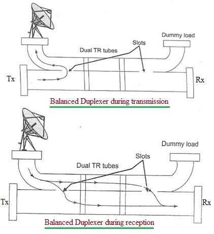
Figure 2: Block diagram of a Balanced duplexer
-
Description: The Balanced duplexer typically consists of two waveguide sections coupled through slots along their narrow walls.
-
Operation:
- Transmitting: The TR tube fires and reflects the incident power. Any energy that leaks through the TR tube is directed to a dummy load, preventing it from reaching the receiver.
- Receiving: During reception, the TR tube doesn’t fire, allowing energy from the antenna to reach the receiver.
- The Balanced Duplexer behaves like a broadband directional coupler.
-
Advantages:
- Higher power handling capability compared to the Branch duplexer.
- Supports higher bandwidth.
Circulator Duplexer
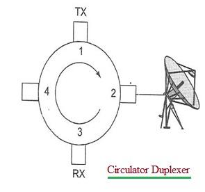
Figure 3: Block diagram of a Circulator duplexer
-
Description: The Circulator duplexer uses a circulator, often with four ports, for duplexing. Typically, port 4 is terminated.
-
Operation:
- The transmitter connects to port 1, the receiver to port 3, and the antenna to port 2.
- The circulator is designed to have low attenuation from port 1 to port 2 (transmitter to antenna) and from port 2 to port 3 (antenna to receiver).
- It provides high attenuation in the reverse directions (e.g., port 2 to port 1, port 3 to port 2).
- This allows the transmitter to efficiently send signals to the antenna and the receiver to efficiently receive signals from the antenna.
Advertisement


