 RF
RFRF Switch Matrix: Advantages and Disadvantages
Advertisement
This page explores the advantages and disadvantages of RF Switch Matrices, covering their benefits and drawbacks.
What is an RF Switch Matrix?
Introduction: An RF switch matrix contains RF switches (Electro-Mechanical or Solid State) housed in a mechanical enclosure. It features multiple inputs and outputs, enabling the routing of RF signals. In addition to RF switches, it may include signal conditioning components like attenuators, amplifiers, filters, couplers, dividers/combiners, etc.
RF switch matrices can be categorized mainly into two types:
- Blocking Type: Developed using solely RF switches. In this configuration, an input signal can only be connected to a single output port. This input port is blocked from use by all other output ports. Unused ports also block connectivity to other RF switches. Different RF switch configurations are employed, such as SPST, 1P2T (SPDT), 1P3T, 1P4T, 1P6T, etc.
- Non-Blocking Type: Constructed using RF switches and RF power combiners/dividers. Here, each input port is available to all output ports, regardless of whether it’s already connected to an output port.
JFW Industries, Inc. is a manufacturer of RF switch matrices for various applications.

Image Courtesy: JFW Industries, Inc., Indianapolis, IN 46237, Visit : <www.jfwindustries.com>
Applications of RF Switch Matrices
Here are some applications of RF switch matrices:
- 16:1 Switch matrix: Used to route multiple satellite TV feeds to an RF spectrum analyzer for signal integrity testing. This design utilizes five SP4T coaxial Electro-mechanical switches.
- Switch matrix: Used to measure the jitter of multiple high-speed serial data links simultaneously.
- TV reception and re-broadcasting
- Test and Measurement: Used for testing Transmit/Receive functionalities of a Device Under Test (DUT) using an RF Signal Generator (RFSG) and RF Signal Analyzer (RFSA) such as Spectrum Analyzer, Frequency counter, or Power meter.
- Satellite Ground Station Systems: Used at Hub stations, e.g., Modem Switch Over Unit (SWO), Frequency Converter SWOs for Up converters and Down converters, etc.
RF Switch Matrix Modules
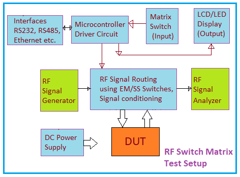
Figure-1 depicts a block diagram of RF switch matrix modules:
- RF Signal Routing and Conditioning: This involves RF switches and RF flexible or rigid cables for RF signal routing. RF switches can be either Electro-mechanical or Solid State, depending on desired specifications. Electro-Mechanical RF switches rely on mechanical contacts for switching, while Solid State RF switches use PIN diodes, GaAs FETs, or a combination of both. RF signal conditioning components include RF amplifiers, attenuators, filters, power splitters, directional couplers, mixers, etc. Based on impedance, input and output connectors can be of various types, such as SMA, BNC, and N-type.
- Microcontroller Hardware and Software: Microcontroller ICs like the STM32L4 series or LPC2148 can be used as per custom RF switch matrix design. External EPROM and/or flash RAM are used based on the size of the source code and data in the program.
- Matrix Switch or Keypad: A 4x4 keypad is typically used for providing user input for monitoring and controlling the RF switch matrix.
- LCD/LED Display: An appropriate LCD/LED display is used to provide a menu for various operations.
- DC Power Supply: Provides supply voltages to RF switches, microcontroller driver, keypad, LCD/LED display, etc.
- Interfaces: Various serial interfaces, such as RS232 and RS485, are used based on the design. An Ethernet port is provided for remote monitoring and control using TCP/IP protocols.
Benefits or Advantages of RF Switch Matrix
Following are the benefits or advantages of RF Switch Matrix:
- It consolidates connections of all test equipment to a central point, simplifying and expediting DUT testing.
- Measurements are automated and stored in files with minimal manual intervention, reducing testing time and the need for constant manpower.
- Calibration is streamlined due to the short signal path between the DUT and test equipment (VSA - Vector Signal Analyzer or VSG - Vector Signal Generator).
- Proximity of the DUT and test equipment minimizes path loss and signal degradation, which helps in meeting receiver sensitivity requirements of test equipment (spectrum analyzer, network analyzer, VSA).
- Remote monitoring and control are possible via a LAN Ethernet port, enabling remote testing after DUT connection and power-up. This allows global access to test labs for multiple test engineers.
Drawbacks or Disadvantages of RF Switch Matrix
Following are the drawbacks or disadvantages of RF Switch Matrix:
- High port to port isolation is crucial for accurate results.
- Non-blocking RF switch matrices generally have higher insertion loss compared to blocking types.
- Readily available RF switch matrices may not always meet specific testing needs, requiring custom designs that can be costly in terms of labor and money.
- Operating RF switch matrices for different applications requires training for test technicians.
Advertisement


