 RF
RFWeightless Physical Layer : Transmitter & Receiver
Advertisement
As described in the OSI protocol stack, the physical layer provides services to the MAC layer and upper layers. It also handles functionalities like Forward Error Correction, modulation, and scrambling to ensure reliable data transmission from the transmit to the receive end.
This article explores the weightless physical layer, a wireless technology primarily aimed at IoT (Internet Of Things) and M2M (Machine to Machine) communication. A weightless system comprises two main components: a base station and terminals. Transmission from the base station to the terminals is called downlink, while the reverse is called uplink.
The weightless specifications define two physical layer variants: high rate downlink and standard rate downlink. This article will walk through the modules of the high rate downlink weightless physical layer transmitter. The standard rate downlink physical layer does not use a cyclic prefix insertion module.
Weightless Physical Layer Transmitter
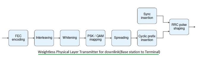
As depicted, the transmitter part of the weightless physical layer includes FEC encoding, interleaving, whitening, PSK/QAM modulation types, spreading, cyclic prefix insertion, sync insertion, and RRC pulse shaping. Let’s understand these modules.
The following Table 1 shows data rates supported for various FEC rates, modulation types, and spreading factors in the weightless system. These data rates assume an 8MHz channel bandwidth and 20% overheads (for synchronization sequences, cyclic prefixes, and cyclic postfixes).
| Modulation type | FEC rate | Spreading factor | Physical layer data rate (after overheads) |
|---|---|---|---|
| 16-QAM | None | 1 | 16 Mbps |
| 16-QAM | 3/4 | 1 | 12 Mbps |
| 16-QAM | 1/2 | 1 | 8 Mbps |
| π/4 QPSK | 3/4 | 1 | 6 Mbps |
| π/4 QPSK | 1/2 | 1 | 4 Mbps |
| π/2 BPSK | 3/4 | 1 | 3 Mbps |
| π/2 BPSK | 1/2 | 1 | 2 Mbps |
| π/2 BPSK | 1/2 | 2 | 1 Mbps |
| π/2 BPSK | 1/2 | 4 | 0.5 Mbps |
| π/2 BPSK | 1/2 | 8 | 0.25 Mbps |
| π/2 BPSK | 1/2 | 16 | 0.125 Mbps |
FEC Encoding: This module adds redundant bits to the MAC layer data. These extra bits help in error correction at the receiver. A Rate-1/2 convolutional encoder generates 2 bits of output data for every 1 input bit. Other rates are achieved through a technique called puncturing.
Interleaving: The interleaving module may or may not exist, depending on the FEC encoder module’s availability. Interleaving provides time diversity, increasing robustness in the presence of a time-varying channel alongside forward error correction. See Interleaver and deinterleaver basics with MATLAB code used in an OFDM system. In weightless systems, the interleaver is a block interleaver, a matrix of 8 columns and a variable number of rows. The number of rows depends on the spreading factor used.
| Spreading factor | Interleaver rows (N row) |
|---|---|
| 1, 2, 4, 8 | 16 |
| 15, 31, 63 | 8 |
| 127, 255 | 4 |
| 511, 1023 | 2 |
Input bits are written into the matrix row by row, starting at row 0 and column 0. The final matrix is padded with zero values if not entirely filled with data values. The interleaver output is obtained by reading the permuted matrix column by column, starting from column 0 and row 0.
Whitening: This module randomizes the bit stream by multiplying it with a known random sequence, making the resulting sequence resemble white noise. This removes long streams of ones and zeros, aiding synchronization at the receiver. It’s similar to a scrambler. See white noise vs. colored noise for more information.
PSK/QAM Modulation: The modulation block in the weightless physical layer maps binary bits into complex symbols. 16-QAM, π/4 QPSK, and π/2 BPSK modulation types are used. PSK (Phase Shift Keying) varies the phase of the RF carrier according to the baseband binary information bits being transmitted. BPSK is a type of PSK. QAM (Quadrature Amplitude Modulation) varies both amplitude and phase of the RF carrier. In BPSK, each symbol represents 1 bit, while in QPSK, each symbol represents 2 bits.
Spreading: As mentioned, spreading occurs after the mapping block. This is needed to generate a chip sequence. To reduce the PAPR of the modulated chip sequence, π/2 rotation is applied to the BPSK chip sequence, and π/4 rotation is applied to the QPSK chip sequence by multiplying the symbol sequence by exp(sqrt(-1)*φ(n)). When a spreading module is used, this is done after spreading the data packet. In the spreading module, each data symbol is repeated by the spreading factor. This result is then multiplied with a spreading sequence obtained using LFSR. The LFSR in the weightless physical layer is of length 16 m sequence with the polynomial:
X16 + X14 + X13 + X11 + X0
The seed is initialized with the bitwise logical OR of 0x8000 with the 16-bit BS_ID (Base Station Identifier) and reset at the beginning of each burst.
Cyclic Prefix Insertion: This module copies the last few samples of the frame to the start of the frame. This allows the received time-domain frame to be converted to the frequency domain without corruption from multipath transmissions. See Cyclic Prefix basics for details. Downlink transmissions (from base station to terminals) are partitioned into blocks of chips, each having a cyclic prefix and cyclic postfix.
| Core Block size | 1024 chips |
|---|---|
| Cyclic prefix | 144 chips |
| Cyclic postfix | 16 chips |
Sync Insertion: This is similar to a preamble, also called a sync pattern. These are known patterns of bits used at the receiver for synchronization.
RRC Pulse Shaping: This module reduces out-of-band radiations. It converts the information data bits in the form of a square wave into a sinusoidal pulse shape. RRC (Root Raised Cosine) is a digital filter.
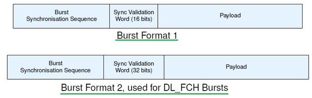
As shown in Figure 2, weightless data bursts consist of a burst synchronization sequence (variable length), a synchronization validation word (16 bits except for DL_FCH and 32 bits for DL_FCH), and a payload. FEC encoding, interleaving, and whitening modules are not used for the Synchronization validation word, but spreading is applied.
Weightless Physical Layer Receiver
Front-end Synchronization: The burst synchronization sequence is transmitted at the start of each burst. This is used for the following front-end synchronization modules in the receiver:
- Coarse Time offset estimation and correction to find the start of the burst.
- Fine frequency offset estimation and correction.
- Channel estimation and equalization.
- Timing detection to determine the payload’s starting position.
The burst synchronization sequence consists of 128 chips followed by 3 termination blocks formed by negating both I and Q values. The rest of the modules reverse the functions performed in the weightless physical layer transmitter.
The receiver consists of front-end synchronization, followed by cyclic prefix removal, de-spreading, de-mapping, de-whitening, de-interleaving, and FEC decoding.
Advertisement


