RF Transceiver Measurements and Testing
Advertisement
This page describes how to test an RF Transceiver, covering measurements like gain, 1dB compression point, spurious emissions, harmonics, S parameters, and more.
This information will help RF engineers test transceiver specifications against compliance requirements using equipment such as spectrum analyzers, signal generators, and power meters. An RF Transceiver is a device that combines both a transmitter and a receiver.
An RF Transmitter carries modulated information (voice, data, image, video) over a specific RF frequency to a distant end.
An RF Receiver demodulates the information from the received RF signal and feeds it to the demodulator.
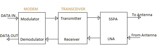
Figure: Location of RF Transceiver in a wireless communication system.
As shown in the figure, the transmitter is interfaced between the modulator and the power amplifier (PA). It’s often referred to as an up-converter. The receiver is interfaced between the LNA (Low Noise Amplifier) and the demodulator, and is known as a down-converter.
The following table outlines useful RF transceiver measurements for C band applications. The specifications are categorized into RF up-converter and RF down-converter sections. The following sections describe how to test the RF Transceiver measurements detailed below.
| RF Up converter Specifications | Typical value |
|---|---|
| Output frequency Range | 5.925 to 6.425 GHz |
| IF input frequency Range | 52 to 88 MHz |
| RF Output | 0 dBm |
| 1dB compression point | +3 dBm |
| Conversion Gain | 20dB (min.) |
| Gain Flatness | +/- 1 dB over +/-18 MHz |
| Gain Variation | Within +/- 1 dB over 0 to 50 DegreeC |
| Gain adjustment | 5dB |
| Spurious and harmonics output | Better than -40dBc over +/-18 MHz |
| Gain Flatness | +/- 1 dB over +/-18 MHz |
| Frequency Stability | +/- 1*10 -6 over temp. 0 to 50 DegreeC |
| Long Term Frequency Stability | +/- 1*10 -7 per day |
| RF Down converter Specifications | Typical value |
|---|---|
| RF Input frequency Range | 3.7 to 4.2 GHz |
| RF Output frequency Range | 52 to 88 MHz |
| Conversion Gain | 40 dB |
| Input level | -40 dBm to -85 dBm |
| Gain Flatness | +/- 1dB over +/- 18MHz |
| Gain Variation | +/- 1dB over 0 to 50 DegreeC |
| Gain Adjustment | 5dB |
| Noise Figure | Better than 14 dB |
| Spurious Output | Better than -40 dBc |
| Image rejection | 50 dB min. |
RF Transceiver Test Procedure - How to test RF Transceiver
All the above measurements are carried out using a Spectrum Network Analyzer (SNA), or a combination of signal generator with a power meter/spectrum analyzer.