5G Cell Phone Architecture: A Block Diagram Overview
Advertisement
The hardware architecture of the latest generation of mobile phones has advanced significantly with the advent of 5G NR (New Radio) and 6G wireless technologies. The core design and components in a 5G-enabled mobile phone block diagram reflect these innovations, enhancing connectivity, speed, and overall performance.
In this article, we’ll delve into the structure and functionality of each component in a 5G cell phone, providing a detailed view of how modern mobile devices are designed to handle high-speed data, low latency, and improved network efficiency.
Introduction
5G cell phones have been designed to comply with either 3GPP NR or Verizon TF specifications. Some phones support both.
They operate on radio frequencies in various bands, depending on country-specific allocations. Typically, this includes frequencies below 1 GHz, below 6 GHz, and above 6 GHz (i.e., mmWave). 5G delivers fast uplink/downlink throughput due to massive MIMO and lower latency between the 5G network (i.e., 5GNB) and the phone itself.
A 5G cell phone supports approximately 10 times the throughput of 4G phones. They are backward compatible with 4G standards such as LTE and LTE-Advanced.
Moreover, the latest 5G phones support Bluetooth, Wi-Fi, and NFC-based short-distance wireless technologies. GPS is also incorporated to support various GPS-based applications, including location tracking and Google Maps.

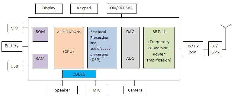
Figure 1: GSM Cell Phone Block Diagram
Figure 1 depicts a block diagram of a GSM cell phone. As shown, it consists of an RF section including the RF Transceiver chip and a baseband section comprising a DSP and CPU for controlling data/control messages. ADC/DAC chips interface both RF and baseband sections.
Other basic cell phone components include a touchscreen display, battery, RAM, ROM, RF antenna, MIC, Speaker, camera, diplexer, micro-USB, SIM slots, and more.
5G Cell Phone Architecture
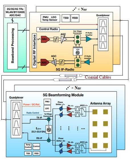
Figure 2 depicts a basic block diagram of 5G cell phone architecture.
As shown, the architecture includes a baseband section, a digital RF interface such as DigRF, ADC/DACs, and an RF Transceiver. The basic components are the same as in 5G phones, except an antenna array is used instead of a single antenna to support massive MIMO and beamforming. A quadplexer is used instead of a diplexer to support multiple bands. A quadplexer is used to multiplex and demultiplex four radio frequencies to/from a single coaxial cable, as shown. This helps reduce cost and weight, as well as utilize a smaller area within the phone.
This 5G cell phone architecture supports mmWave frequency bands.

Figure 2: 5G Cell Phone Architecture
To support massive MIMO/beamforming, multiple PAs (Power Amplifiers), LNAs (Low-Noise Amplifiers), phase shifters, RF filters, and SPDT (Single-Pole Double-Throw) switches are incorporated into the 5G cell phone design. The 5G phone is backward compatible with 2G/3G/4G, WLAN, Bluetooth, GNSS, etc.
The 5G phone shown is based on heterodyne architecture. Radio Frequency Front End (RFFE) control signals are used to carry TSSI (Transmitter Signal Strength Indicator) and RSSI (Receiver Signal Strength Indicator) information. As a result, temperature control and calibration of the beamforming module are performed.
PMUs (Power Management Units) and LDOs (Low Drop-Out Regulators) are used in the beamforming part of the 5G cell phone. They transform the DC voltage of the coaxial cable to different power supplies for use in various dies for cell phone operation.
Conclusion
In conclusion, the 5G mobile phone block diagram provides a foundational view of how modern devices achieve remarkable speeds, connectivity, and capabilities. Each component, from the antenna to the processing units, is tailored to meet the demands of 5G networks, offering users an unparalleled mobile experience.
As 5G technology continues to evolve, so will the architecture of mobile devices, setting the stage for future innovations in connectivity and performance. Understanding these fundamentals equips us to appreciate the sophistication of today’s mobile devices and anticipate the exciting advancements yet to come.
Reference
The figure-2 has been modified for demostration purpose from the paper published on “5G Cellular User Equipment: From Theory to Practical Hardware Design” which is published on July 18,2017 at IEEE Access by YIMING HUO1, XIAODAI DONG1 and WEI XU2.
Advertisement
 RF
RF


