Arduino Interfacing with LDR Sensor: Guide and Code
Advertisement
This article explains how to interface an LDR (Light Dependent Resistor) sensor with an Arduino board, including a wiring diagram, explanation of how it works, and example Arduino code.
Introduction
LDRs are widely used in a variety of applications, including power saving systems, smart escalators, smart lighting, automatic urinal flushing systems, camera shutter control, and light-activated switches. This guide will show you how to connect and use an LDR with an Arduino Uno board.
About the LDR Sensor
An LDR, or Light Dependent Resistor, is a component whose resistance changes depending on the amount of light falling on it. This makes it useful for light-sensing circuits. LDRs are employed when monitoring light intensity is required.
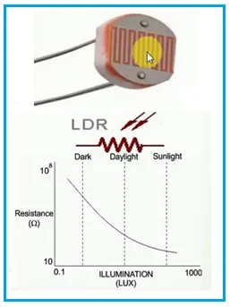
Figure: LDR Illumination vs. Resistance Curve and LDR Symbol
As shown in the figure, the sensor’s resistance varies with the intensity of light, which in turn causes the output voltage to change. The Arduino board can be used with the LDR sensor to read this analog voltage. By programming a threshold value in the code and reading the real-time voltage values from the LDR sensor, you can determine whether it’s dark or bright.
About the Arduino Board
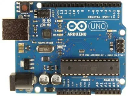
Figure: Arduino Uno Board
- The Arduino Uno features an ATmega328 microcontroller from ATMEL. This microcontroller has 32 KB of flash memory, 2 KB of RAM, an 8-bit CPU, and 1 KB of EEPROM.
- It also offers 6 analog pins, which read voltage (not current). Internally, it converts the analog measurement to a digital value.
- It provides digital pins (0 to 13) that can function as either inputs or outputs.
- It has various interfaces, including I2C, digital pins, analog pins, serial communication, and USB.
- It also has a reset pin, a power port, a crystal oscillator, and Tx/Rx LEDs.
- This open-source prototyping board can be easily programmed using the Arduino IDE and a USB connection between a laptop/PC and the Arduino board.
- The IDE uses a simplified C++ program.
- The board requires 5V DC, which can be supplied via an AC/DC adapter or a battery.
Arduino Interfacing with LDR Sensor: Diagram and Working
The following diagram illustrates how to interface the Arduino Uno board with an LDR, connecting to the 5V, GND, and A0 pins.
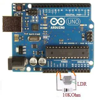
Figure: Arduino Interfacing with LDR Sensor
You can also use other boards like ESP32, ESP8266, or any microcontroller board for interfacing the LDR sensor through an analog read input. A resistor (typically 10k Ohm) is used in series with the LDR to create a voltage divider.
The voltage at the analog pin (A0 in this example) will vary based on the light hitting the LDR. When light is high, the LDR’s resistance is low, and the voltage at A0 is higher. When light is low, the LDR’s resistance is high, and the voltage at A0 is lower.
The voltage () at the analog pin can be calculated using the voltage divider formula:
Where is the supply voltage (5V in this case), is the resistance of the fixed resistor (10k Ohm), and is the resistance of the LDR.
Arduino LDR Sensor Interface Code
Below is the Arduino code to be compiled and uploaded to the Arduino board using the Arduino IDE.
#define LDRpin A0  // pin of the arduino board i.e. A0 where LDR sensor and resistor are connected
int LDRValue = 0;  // Variable where LDR sensor reading is stored

void setup() {
  Serial.begin(115200);  // baud rate setting for serial port communication
}

void loop() {
  LDRValue = analogRead(LDRpin);  // reading from LDR sensor
  Serial.println(LDRValue);       // Print value on serial port
  delay(100);                     // wait for some period and keep printing
}
Explanation:
#define LDRpin A0: This line defines the analog pin A0 as the pin connected to the LDR sensor.int LDRValue = 0;: This line declares an integer variableLDRValueto store the analog reading from the LDR.Serial.begin(115200);: This initializes the serial communication at a baud rate of 115200, allowing you to view the sensor readings in the Serial Monitor.LDRValue = analogRead(LDRpin);: This line reads the analog value from the LDR sensor connected to the specified pin (A0) and stores it in theLDRValuevariable. The value will range from 0 to 1023, corresponding to voltages from 0V to 5V.Serial.println(LDRValue);: This line prints theLDRValueto the Serial Monitor.delay(100);: This line introduces a delay of 100 milliseconds between readings.
Conclusion
In this guide, we’ve covered how to interface an LDR sensor with an Arduino Uno board. Arduino boards are commonly used for interfacing with various types of sensors for a wide range of applications. Typical sensors interfaced with Arduino include sound sensors, gyro sensors, heartbeat sensors, gas sensors, GPS sensors, color sensors, and pH sensors, among others.