 RF
RFAUTOSAR Tutorial: Architecture Basics Explained
Advertisement
This AUTOSAR Tutorial describes AUTOSAR Architecture Layers and their functions. The tutorial on AUTOSAR describes AUTOSAR basics, AUTOSAR architecture components, Ports, Interfaces, communication patterns etc. The AUTOSAR Layers viz. application layer, RTE (Runtime Environment), Basic software (Microcontroller abstraction layer, ECU abstraction layer, Services layer, complex drivers) are also explained.
What is AUTOSAR?
Introduction
- AUTOSAR is an alliance of more than 150 companies of automotive manufacturers and automotive suppliers.
- It is short for AUTomotive Open System ARchitecture.
- The aim of AUTOSAR is to establish an open and standardized automotive software architecture.
- It simplifies automotive software development.
- AUTOSAR helps in managing product modifications, reliable upgrades, reusability, and scalability in software development.
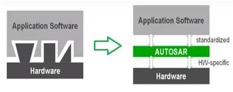
- Due to innovations in the automotive electronics industry, software of ECU (Electronic Control Unit) is highly dependent upon hardware. This leads to higher costs and more effort for the relocation of functions between ECUs.
- AUTOSAR introduces a standardized layer between application software and ECU (i.e., hardware). This makes software independent from the chosen microcontroller and OEM. This simplifies development processes and helps in the reuse of application software.
- AUTOSAR covers the following working topics which are software architecture, methodology, and application interfaces. The standardized layer is called the “Basic software” layer in the AUTOSAR architecture as explained below.
AUTOSAR Architecture Layers
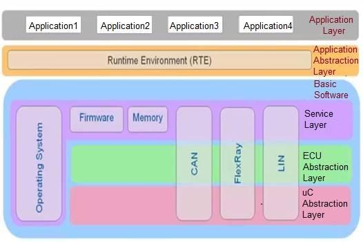
Let us understand AUTOSAR architecture layers as part of this AUTOSAR tutorial. As shown in Figure 2, the AUTOSAR architecture has 3 main layers viz. Application layer, RTE, and basic software. The basic software consists of many sublayers viz. service layer, ECU abstraction layer, and microcontroller abstraction layer. These three sublayers of the “basic software” layer offer modules with different service functions such as OS services, network communication, memory services, management services, etc. Moreover, various bus types exist across these three sublayers which include CAN, LIN, Flexray, MOST etc.
Application Layer
The application layer consists of interconnected software components. A software component is a reusable self-contained artifact which implements a function with given properties. These software components encapsulate parts of the application and communicate over a hardware-independent bus called VFB (“Virtual Functional Bus”). If software components are tied to different ECUs, then they can communicate via their respective RTEs and basic software layers. In this case, RTE implements VFB on a dedicated ECU. The “Basic software” offers various service functions for application developers.
Virtual Functional Bus
The virtual functional bus is the abstraction of the AUTOSAR Software Components interconnections of the entire vehicle. The communication between different software components and between software components and its environment (e.g., hardware driver, OS, services, etc.) can be specified independently of any underlying hardware (e.g., communication system). The functionality of the VFB is provided by communication patterns.
RTE (Runtime Environment)
- All interaction between AUTOSAR Software Components is routed through the AUTOSAR Runtime Environment. The AUTOSAR Interface specification assures the connectivity.
- The AUTOSAR Runtime Environment (RTE) acts as a system-level communication center for inter- and intra-ECU information exchange.
- The RTE is the runtime representation of the Virtual Function Bus for a specific ECU.
- The RTE provides a communication abstraction to AUTOSAR Software Components providing the same interface and services for inter-ECU (using CAN, LIN, Flexray, MOST, etc.) or intra-ECU communication.
- As the communication requirements of the software components are application-dependent, the RTE needs to be tailored.
- The RTE shall support multiple instantiations of software components.
Basic Software
-
An AUTOSAR Software Component is not allowed to access Basic Software directly.
-
Basic Software is the standardized software layer, which provides services to the SW Components. It does not fulfill any functional job and is situated below the AUTOSAR Runtime Environment. It contains standardized components and ECU-specific components.
-
The standardized components include the following:
- Services including diagnostic protocols; NVRAM, flash and memory management.
- Communication the communication framework (e.g., CAN, LIN, FlexRay…), the I/O management, and the network management.
-
The ECU-specific components include the following:
- Operating system
- Microcontroller abstraction
- Complex Device Drivers
AUTOSAR Components, Ports, Interfaces
SW Component: A reusable self-contained artifact implementing a function with given properties. A component has well-defined ports, through which the component can interact with other components.
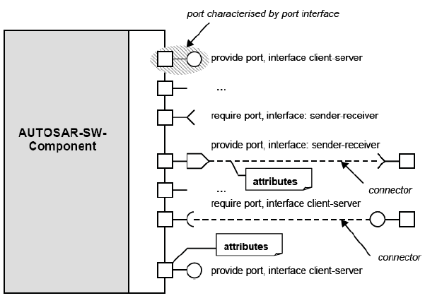
Port: A port always belongs to exactly one component and represents a point of interaction between a component and other components. To define the services or data that are provided on or required by a port of a component, the AUTOSAR Interface concept is introduced.
Interfaces: The AUTOSAR Interface can be either client-server or sender-receiver type.
- Client-Server Interface defining a set of operations that can be invoked.
- Sender-Receiver Interface, for data-oriented communication.
A port can be:
- PPort (provided interface)
- RPort (required interface)
When a PPort provides an interface, the component to which the port belongs:
- provides an implementation of the operations defined in the Client-Server Interface
- generates the data described in a data-oriented Sender-Receiver Interface.
When an RPort of a component requires an AUTOSAR Interface, the component can:
- invoke the operations when the interface is a Client-Server
- read the data elements described in the Sender-Receiver Interface.
AUTOSAR Communication Patterns
Elementary communication patterns:
- Client-Server
- Sender-Receiver
Interfaces specify:
- what information sender receiver communication transports
- which services with which arguments can be called by client-server communication
The formal description of the interface is in the software component template, including also data types that can be used and interface compatibility.
The detailed behavior of a basic communication pattern is specified by attributes. With those attributes e.g. the length of data queues and the behavior of receivers (blocking, non-blocking, etc.) and senders (send cyclic, etc.) can be defined.
Client-Server communication
The server is a provider and the client is a user of a service. The client initiates the communication, requesting that the server performs a service, transferring a parameter set if necessary. The server waits for incoming communication requests from a client, performs the requested service and dispatches a response to the client’s request.
The direction of initiation is used to categorize whether an AUTOSAR Software Component is a client or a server. A single component can be both a client and a server depending on the software realization.
After the service request is initiated and until the response of the server is received The client can be:
- blocked (synchronous communication)
- non-blocked (asynchronous communication).
Sender-Receiver communication
Model for the asynchronous distribution of information where a sender distributes information to one or several receivers. The sender is not blocked (asynchronous communication) and neither expects nor gets a response from the receivers (data or control flow), the sender just provides the information and the receivers decides autonomously when and how to use it.
It is the responsibility of the communication infrastructure to distribute the information. The sender does not know the identity or the number of receivers
AUTOSAR Architecture with Example
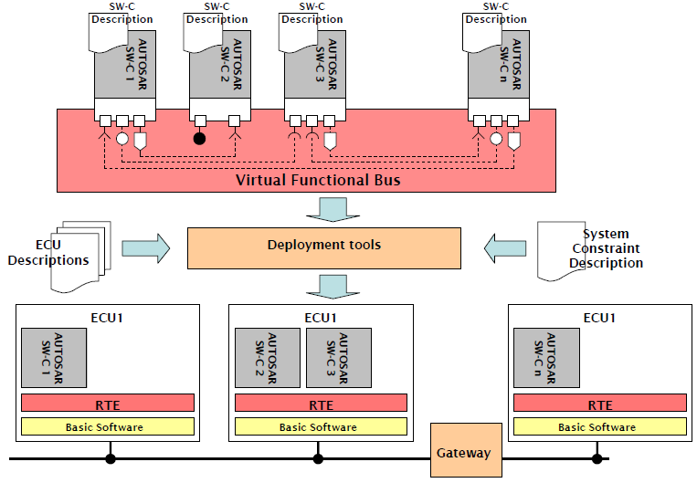
The figure depicts AUTOSAR architecture with example implementation.
Conclusion
This AUTOSAR tutorial for beginners covers AUTOSAR basics including various aspects of AUTOSAR architecture with example, autosar layers etc.
Advertisement


