 RF
RFLatch vs. Flip-Flop: Key Differences Explained
Advertisement
This article breaks down the differences between latches and flip-flops, two fundamental building blocks in digital circuits. We’ll explore their functionalities and highlight when to use each.
SR Latch with Enable
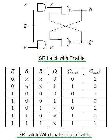
Fig-1: SR Latch with Enable
The diagram above shows an SR latch implemented using NAND gates and an enable input.
- When E = 1 (Enable is active), the circuit acts like a regular SR latch using NAND gates, but with active-high S and R inputs. This means that a high signal on S will set the latch, and a high signal on R will reset it.
- When E = 0 (Enable is inactive), the latch holds its previous state, ignoring any changes to the S and R inputs.
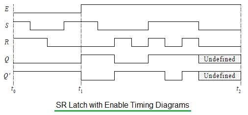
The timing diagram illustrates how the latch responds to changes in the S, R, and E inputs.
- Between
t0andt1,E = 0, so changes to the S and R inputs have no effect on the output. - Between
t1andt2,E = 1, so changes to S and R do affect the output.
Keep in mind that the enable input can be active-high or active-low and might be labeled as ENABLE, CLK, or CONTROL, depending on the specific circuit.
SR Flip-Flop
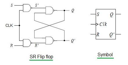
Fig-2: SR Flip-Flop
In the SR latch, the output changes as soon as the enable signal is active. This is known as level-triggered operation.
In contrast, the SR flip-flop shown above responds only to edges of a clock signal. Essentially, we’ve replaced the enable input of the latch with a clock input. The circuit only acts as a flip-flop when the clock transitions from low to high or high to low (depending on the design). The circuit is only operational during these edge transitions.
Master-Slave SR Flip-Flop
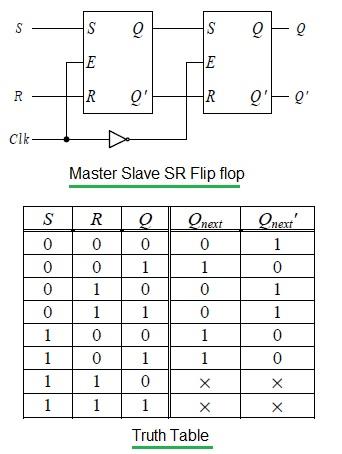
Fig-3: Master-Slave SR Flip-Flop
Both latches and flip-flops are useful for storing data bits and for setting and resetting the bit. However, flip-flops only change their state on the active edge of a clock signal.
Like their latch counterparts (SR latches), SR flip-flops can enter an undefined state if both inputs are asserted simultaneously.
Key Differences: Latch vs. Flip-Flop
The following table summarizes the key differences between latches and flip-flops:
| Feature | Latch | Flip-Flop |
|---|---|---|
| Basic Function | Bistable device storing either 0 or 1. | Bistable device storing either 0 or 1. |
| State Change | Changes state as soon as the input is given; doesn’t depend on a control input or clock. | Changes state only during the active edge (or level, depending on the type) of a clock signal. |
| Clock Dependency | No clock is present. | Clock signal controls the operation. |
| Control | Operation is uncontrolled unless an enable signal is used. With the enable signal, the latch is often referred to as a “gated latch”. | Operation is controlled by the clock signal. |
| Triggering | N/A | Triggered by an edge (low-to-high or high-to-low transition) or, in some cases, by a pulse. Positive edge triggered or negative edge triggered. |
| Examples | D latch, T latch, SR latch, JK latch | D flip-flop, T flip-flop, SR flip-flop, JK flip-flop |
In essence, latches are level-sensitive, while flip-flops are edge-triggered. This fundamental difference dictates their use in various digital circuits. Flip-flops provide more precise timing control and avoid race conditions, making them suitable for synchronous systems.
Advertisement


