 RF
RFWeightless System: Basic Overview for IoT
Advertisement
As we know, the Internet of Things (IoT) has become popular for machine-to-machine communication. Due to the requirement of low cost, longer battery life, and the use of existing TV white space spectrum, the development of many wireless standards has been pioneered.
The Whitespace radio spectrum is made available by the regulatory authority for unlicensed use. This falls under the UHF band, approximately between 470 MHz to 790 MHz frequency range based on the country. Typically, TV broadcasting uses an 8MHz channel in Europe and 6MHz in the US.
The Weightless standard has been developed to fulfill these requirements of the IoT system. This standard meets the basic machine requirements as outlined below:
- Need to support a large number of terminals.
- Longer battery life, at least about 10 years.
- Low network and terminal costs, about $2 per chip or even less.
- Efficient small burst transmission, on the order of about 50 bytes.
- Strong authentication and encryption for reliable guaranteed delivery.
- Operation in TV white space which has many merits, such as low levels of out-of-band emissions.
Like other wireless systems, the Weightless system consists of two main parts: network-side systems and user terminals. It consists of a base station, internet backbone systems on the network side, and a terminal having a weightless radio module as well as a protocol stack on the user side.
The Weightless system frame structure is similar to the WiMAX system frame structure, having a TDD topology. The Weightless frame consists of a preamble followed by a downlink part and an uplink part.
Downlink refers to transmissions from the base station to one or more terminals.
Uplink refers to transmissions from terminals to the base station.
Usually, the Weightless frame is of a duration of about 2 seconds.
The frame is divided into slots, which are the smallest possible length of resource allocation to the terminals in the Weightless system. The Weightless system operates with single-carrier modulation, broadband downlink, narrowband uplink, direct sequence spreading, long frame size, and frequency hopping at the frame rate.
The following table-1 mentions the key specifications of the downlink in the Weightless system designed to be used in the IoT network.
| Specification | Weightless system support |
|---|---|
| Multiple Access scheme | TDMA, refer TDD and TDMA |
| Modulation scheme | Single carrier 16QAM, π/4 QPSK, π/2 BPSK |
| Pulse shaping | RRC (beta = 0.4) |
| Chip rate | 5 Mcpc for 8 MHz channels, 4 Mcpc for 6 MHz channels |
| 3dB Signal bandwidth | 5MHz for 8MHz channels 4MHz for 6MHz channels |
| Spreading factor | 1 to 1023, provides a processing gain of 30dB value |
| FEC coding scheme | None, rate 1/2 (convolutional encoding), rate 3/4 |
| Interleaving | Available when FEC encoding is available |
| Whitening | It is based on LFSR (Linear Feedback Shift Register), the seed value is derived from the channel number and frame number |
| Frequency Range | UHF band |
| Channel Bandwidth | 6MHz (America, South Korea, Taiwan, Philippines, Japan) 8MHz (Europe, Africa, Asia, Oceania) |
| Frequency accuracy | The Base Station will maintain a frequency tolerance of +/- 1 ppm When transmitting to the Base Station, a Terminal must achieve a frequency error of less than +/- 100Hz relative to the downlink reception portion of the same frame. |
There are two uplink modes specified in the Weightless system: NB-FDMA (narrowband FDMA) and WB-FDMA (wideband FDMA).
Both of these modes are single carriers and use a burst format as specified in the standard.
Terminals are required to support either of these modes. If both are supported, then it is advantageous.
The following table-2 summarizes key specifications of both of these modes.
| Specification | Narrowband Uplink (NB-FDMA) | Wideband Uplink (WB-FDMA) |
|---|---|---|
| Multiple Access Scheme | Combined FDMA and TDMA | Combined FDMA and TDMA |
| Modulation scheme | Single carrier, 16QAM, π/4 QPSK, π/2 BPSK, single carrier CPM (continuous phase modulation) | Single carrier, 16QAM, π/4 QPSK, π/2 BPSK, single carrier CPM (continuous phase modulation) |
| Pulse shaping | RRC (Beta=0.4), no pulse shaping for CPM | RRC (Beta =0.4), no pulse shaping for CPM |
| Chip Rate | 5/32 Mcps for 8 MHz channels 4/32 Mcps for 6 MHz channels | 5 Mcps for 8 MHz channels 4 Mcps for 6 MHz channels |
| 3dB Sub channel bandwidth | 5/32 MHz for 8 MHz channels 4/32 for 6 MHz channels | 5 MHz for 8 MHz channels 4 MHz for 6 MHz channels |
| Comb finger | - comb finger bandwidth(3dB) : 5/2048 MHz for 8MHz and 4/2048 for 6 MHz channels comb finger separation: 5/64 MHz for 8MHz and 4/64 MHz for 6 MHz channels | No. |
| No. of available subchannels | 22 | 16 |
| Subchannel centre frequency | (2*s+1)*5/32 MHz (8 MHz channels) (2*s+1)*4/32 MHz (6 MHz channels) for s = -11,-10,..+9,+10 (2*s+1)*5/2048 MHz for 8 MHz channals (2*s+1)*4/2048 MHz for 6 MHz channels for s = -8,-7,…,+6,+7 | (2*s+1)*5/2048 MHz for 8 MHz channals (2*s+1)*4/2048 MHz for 6 MHz channels for s = -8,-7,…,+6,+7 |
| Spreading factor | 1 to 256 for PSK/QAM mode, 16 to 256 for CPM mode | 1 to 256 for PSK/QAM mode, 16 to 256 for CPM mode |
| FEC coding scheme | None, rate 1/2 (convolutional encoder), rate 3/4 | None, rate 1/2 (convolutional encoder), rate 3/4 |
| Interleaving | incorporated in the chain when FEC is enabled | incorporated in the chain when FEC is enabled |
| Whitening | Based on LFSR (seed depends on frame number) | Based on LFSR (seed depends on frame number) |
| Frequency accuracy | +/-100Hz for terminal transmission relative to the received downlink frame | +/-100Hz for terminal transmission relative to the received downlink frame |
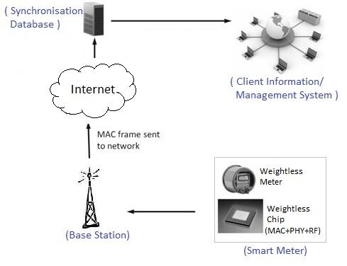
Fig-1 Weightless Network
As shown in the figure, the terminal (e.g., smart meter) will pass the reading information to the weightless PHY/radio module which encodes and transmits the information over the weightless air interface.
There are various modules in the weightless terminal transmitter. Typically, it provides modulation, spreading, and forward error correction functionalities to the data.
The base station receiver receives the downlink frame and does the decoding and passes the frame to the core internet backbone network as per the appropriate format.
The informations transmitted by the terminals are routed via a synchronization database to the client information/management system.
Fig-2 depicts protocol layers at each of these weightless system entities. This is referred to as the Weightless protocol stack.
Weightless System Channel Types
As we know, information between various protocol layers in any system are exchanged using channels. The channels are categorized based on their functionalities, such as control channels, logical channels, transport channels, and physical channels.
There are three physical channels for baseband data processing in the Weightless system. They are the downlink channel, the uplink channel, and the uplink contended access channel.
The downlink physical channel is used to transmit data from the base station to one or multiple terminals in a cell. The uplink physical channel is a dedicated channel used to transmit data from the terminal/terminals to the base station. The uplink contended access physical channel is used for the transmission of data from the terminal to the base station. This channel is used for obtaining access to the network. This channel is used by all the terminals at the same time, hence the name.
The Weightless system uses frequency hopping between the channels at the frame rate. Hence, in the Weightless system, both the uplink and downlink portions of a Weightless frame will use the same channel.
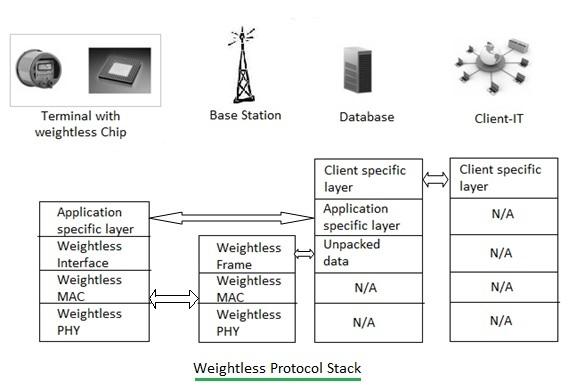
Fig-2: Weightless protocol stack
The figure above mentions the protocol layers of the Weightless system at various entities, such as the terminal, base station, data base, and client system. The core part of Weightless system specifications is the MAC, PHY, and radio layers. As per the requirement, the MAC layer forms the frame after inserting the required header and CRC. This MAC frame is passed to the PHY layer, which incorporates its header used for synchronization (time, frequency, and channel) to the MAC payload. The Weightless PHY layer also incorporates functionalities such as FEC, modulation, spreading, CP insertion, and pulse shaping to the data need to be transmitted over the air.
This PHY encoded data is passed to the radio layer for necessary radio frequency conversion as per the RF channel allocated.
Advertisement


