Impedance Matching: Circuits, Methods, and Devices
Advertisement
This page explores the critical concept of impedance matching, covering various circuits, methods, and devices used to achieve it. We’ll delve into impedance matching circuits such as L networks, pi networks, split capacitor networks, and transmatch circuits. We’ll also examine impedance matching devices, including coaxial cable balun transformers, matching stubs, quarter-wavelength transformers, and series matching sections.
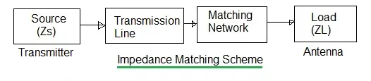
Let’s begin by understanding impedance matching in the context of a radio frequency (RF) antenna used for transmission.
The typical setup involves an RF transmitter connected to a transmission line, which is then connected to an RF antenna. To maximize power transfer in this system, the output impedance of the transmitter must match the impedance of the transmission line. Likewise, the transmission line impedance must match the antenna feed impedance.
Various circuits and methods are employed to achieve this impedance matching.
Since antenna impedance consists of both resistive and reactive components, the matching network must also include both types of elements to provide proper matching.
To match a resistive source with a complex load impedance, the matching network should present the complex conjugate of the complex load impedance. For example, if the load impedance is R + jX, then the matching network should have an impedance of R - jX, and vice versa.
Impedance Matching Circuits
Let’s explore various impedance matching circuits, including L networks, Pi networks, split capacitor networks, and different transmatch circuits.
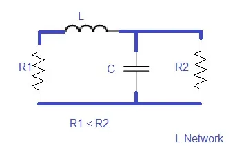
L Network
The L network is a frequently used antenna matching network. Different L section configurations exist, such as inverted L sections and reverse L section networks.
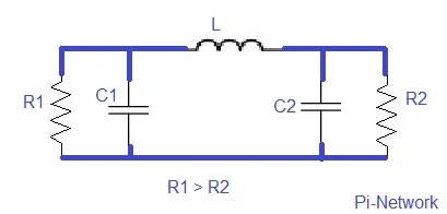
Pi Network
The Pi network is used to match a high source impedance to a low load impedance. These circuits are often used in vacuum tube RF power amplifiers, which require matching to low-value antenna impedances.
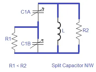
Split Capacitor Network
This network is used to transform a source impedance that is lower than the load impedance.
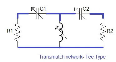
Transmatch Circuit
This circuit combines a split capacitor network with an output tuning capacitor. It’s used for coaxial-to-coaxial impedance matching.
Impedance Matching Devices
Now, let’s examine various impedance matching devices, including coaxial cable balun transformers, matching stubs, quarter-wavelength transformers, and series matching sections.
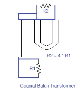
Coaxial Cable Balun Transformer
A balun is a transformer that matches an unbalanced resistive source impedance with a balanced load. For example, the source impedance could be a coaxial cable, and the load could be a dipole antenna. The figure shows a typical circuit. With this type of balun, an impedance transformation ratio of 4:1 can be achieved. The length of the balun section of this coaxial cable can be expressed as:
L (feet) = 492 * V / F (MHz)
Where V is the velocity factor of the coaxial cable.
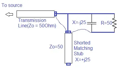
Matching Stubs
A shorted stub can be constructed to produce any desired reactance value. This can act as an impedance matching device that cancels the reactive part of a complex impedance. For example, if we have an impedance of Z = R + j25, then we would need a stub with a reactance value of -j25 Ohms to match it.
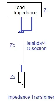
Quarter Wavelength Transformer
The transformer shown can be connected between a transmission line and an antenna load. This transformer is also known as a Q-section.
This transformer is capable of matching a feedline impedance of Zs with an antenna feed impedance of Zr. To achieve impedance matching, the transmission line impedance, Zo, should be equal to (Zs * Zr)^0.5.
There are several disadvantages to using a quarter-wavelength section:
- It must be located at the feedpoint of the antenna.
- It must be a quarter-wavelength long.
- The impedance value must be precisely specified.
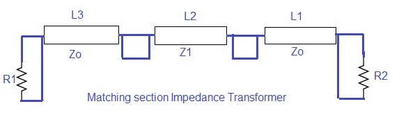
Series Matching Section
This series matching section overcomes the drawbacks of the quarter-wave transformer mentioned above.