 RF
RFCrystal Radio Receiver Basics and Circuit Design
Advertisement
This application note covers the basics of a crystal radio receiver. This receiver circuit is commonly used in crystal radio designs.
The figure below illustrates the circuit of a crystal radio receiver, consisting of an antenna, transformer (T1), tuned capacitor (C1), fixed capacitor (C2), diode, and headphone.
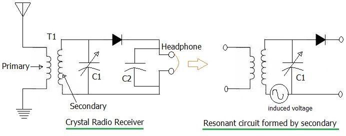
Fig-1: Crystal Radio Circuit
As shown, the antenna picks up the radio signal, causing current to flow in the primary coil of the transformer. This current flow generates a voltage in the secondary coil of the transformer.
This voltage generation is due to the creation of a magnetic field in the secondary coil, induced by the current in the primary windings. Each turn of the secondary coil induces a voltage, essentially acting as a tiny voltage generator. This effect is depicted on the right side of the figure.
It can be represented as a signal generator in series with the secondary coil. As shown, the secondary coil along with capacitor C1 forms a series resonance circuit.
When this circuit is tuned to resonance, a high voltage is produced across the capacitor. This is referred to as resonant step-up voltage. This tuned circuit, with a higher Q factor, can selectively filter out the desired radio frequency.
In this crystal radio receiver circuit, the diode, often referred to as a “crystal,” performs rectification of the input signal.
The capacitor C2 filters out the RF carrier from the received modulated signal. This process removes the carrier, leaving behind the original baseband information.
This recovered audio signal can then be listened to using earphones.
This basic crystal radio receiver doesn’t provide the level of selectivity desired in modern wireless receiver circuits. For improved selectivity, Tuned Radio Frequency (TRF) receiver circuits are designed and used.
Advertisement


